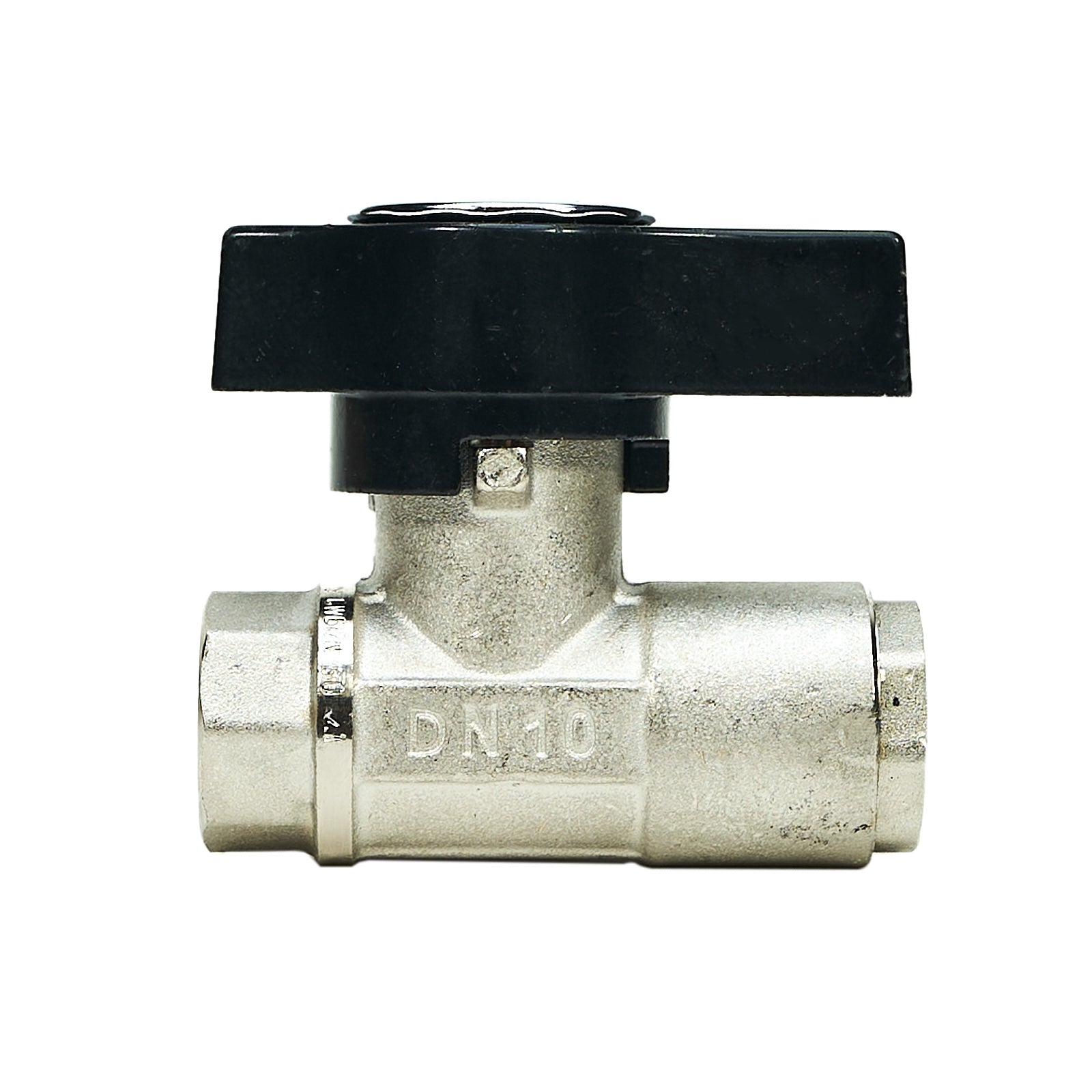
Figure 01 · Field demonstration · 18 secCharles operating a hose-end ball valve. The changing stream is visible; pressure and flow are not measured in this clip.
3,000 PSIMaximum pressure
176 °FMaximum temperature
3/8 in.Female BSP · both ports
8 mmListed bore diameter
Plated-brass body · Made in Italy · Specifications apply to MTM Hydro part 20.0032. Manufacturer reference ↗
The pressure washer produces the flow. A small valve helps determine where that flow goes—and where the operator can stop it.
On my rig, a hose-end ball valve earns its place through repeated use. The MTM Hydro DN10 is useful beyond tool changes: the same shutoff function can serve a chemical-injector bypass or a properly designed trailer circuit.
01
Hose-end shutoff
Temporarily isolate the attached gun or surface cleaner. MTM describes this as a tool-change application. Closing the valve leaves pressure upstream; follow the equipment’s shutdown and pressure-release procedure before disconnecting fittings. [1]
02
Injector bypass
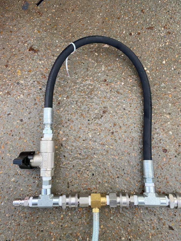
A valve in a parallel branch opens or closes a route around the downstream injector. Its position changes the available flow path. The photograph below shows this arrangement on my custom assembly.
03
Trailer line control
In a suitably designed manifold, a rated valve can isolate an individual branch. It does not add pump capacity or make a single-gun system suitable for multiple operators.
Original photograph supplied by Charles Worthley. Numbered markers identify the visible components.
Flow-path study
What the valve changes
Closed: the parallel route is blocked, so water passes through the injector. Chemical draw still depends on injector sizing and sufficiently low downstream backpressure.
Simplified flow schematic, not a plumbing plan. Direction shown is illustrative; follow the injector’s actual flow marking. Opening the bypass does not physically close the injector branch.
Figure 03 · Operating principle
A quarter turn changes the passage.
A ball valve uses a rotating, bored ball to open or block the water path. This explains its basic value: a short lever movement provides a positive change of state.
The port size, internal passage, and pressure rating describe different things. For part 20.0032, MTM lists a 3/8-inch connection and an 8 mm bore. Neither figure establishes the pressure loss at your rig’s flow rate. [1]
Functional section · not to scale
General ball-valve mechanism only. This schematic does not represent the DN10’s exact seat, seal, or stem assembly and is not an exploded parts drawing.
Field observations
Useful evidence, measured claims.
The video demonstrates hose-end rinsing and a changing spray pattern. It does not measure PSI, GPM, or service life.
Owner discussions show both enthusiasm for DN10 tool changes and differing opinions about direct rinsing. Reported results vary with the machine and setup; added weight and quick-connect leaks also appear in the conversation. These are individual experiences, not a controlled comparison. Read the contractor discussion ↗
Bypass discussions are similarly mixed. Some operators report a useful improvement; others find little difference. That makes a measured comparison on the actual rig more useful than a universal performance claim. Read the bypass discussion ↗
Installation considerations
Match the entire assembly.
Use the rating of the exact valve and every connected fitting. A similarly shaped “DN10” listing is not proof of an identical pressure rating.
BSP and NPT are different thread standards. Select fittings or adapters explicitly approved for this valve; extra tape is not a substitute for a compatible connection. Thread reference ↗
Verify chemical compatibility for the complete valve assembly when chemicals contact it. Closing a hose-end valve can put the pump into bypass; follow the pressure washer’s operating limits. Recirculating water can heat up, particularly when bypass returns to the pump inlet. Pump manufacturer guidance ↗
Charles’s assessment
Its value is control: stopping flow at the tool, opening a route around an injector, or isolating a branch on the rig.
That is why this small component deserves attention. Choose it for the job, match it to the system, and judge it by what it actually does in service.
Want your product reviewed? Contact Charles Worthley at (904) 434-1108.
Sources & technical references
MTM Hydro: part 20.0032 — product identity, material, origin, dimensions, ratings and stated temporary-shutoff application. Checked October 25, 2026.